

Optics Primer, Part 1: Traditional Pluggable Optics
Optical interconnects, pluggable transceivers, optical and electrical engines, DSP overhead, power and latency trade-offs

This is the first in a series we’ll return to periodically with clear explainers on optical interconnects and the photonics technologies behind them.
Traditional Pluggable Optics
AI training workloads are distributed. Large models are split across many GPUs, and those GPUs must constantly exchange activations, gradients, and parameters. That communication does not stay on a single board or even inside a single rack, so switches are required to route traffic between GPUs. For more, catch up here with our GPU Networking Series, Part 1, Part 2, Part 3, Part 4.
Much of that communication happens over optical interconnects. At rack and datacenter distances, data is carried as pulses of light over fiber. Optical signaling scales far better than copper in both distance and bandwidth. At distances 3-7m AECs make copper possible even at today’s 50G and 100G per lane, see Credo AECs and Vik’s AECs in the 1.6T era.
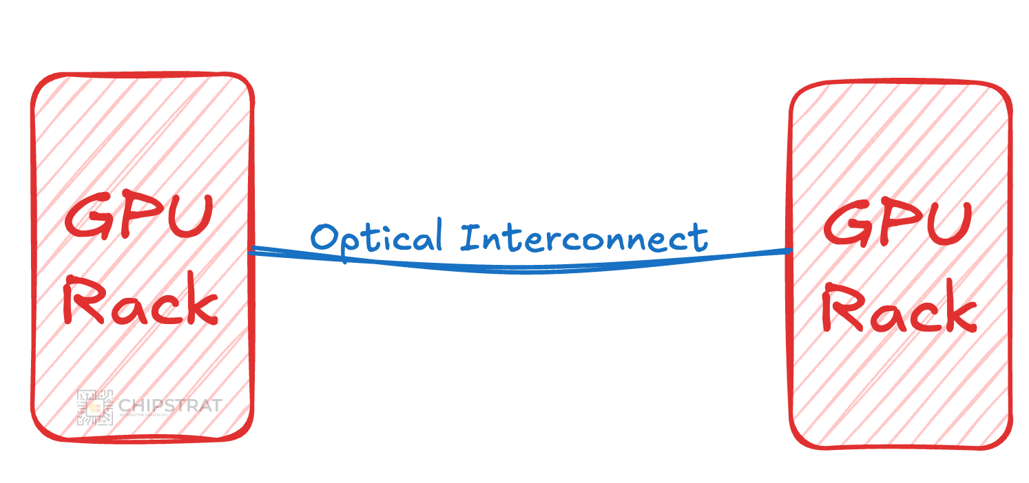
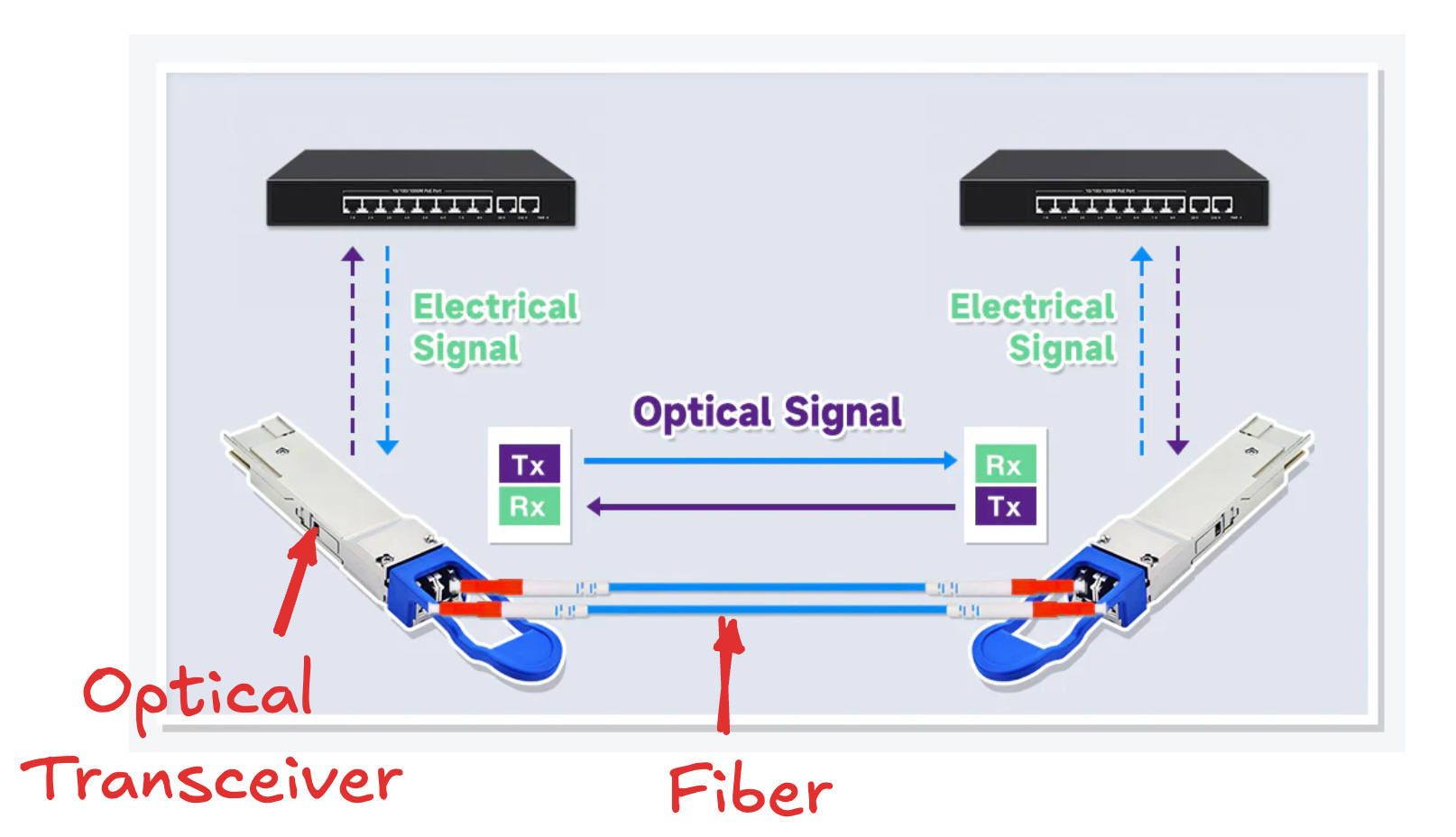
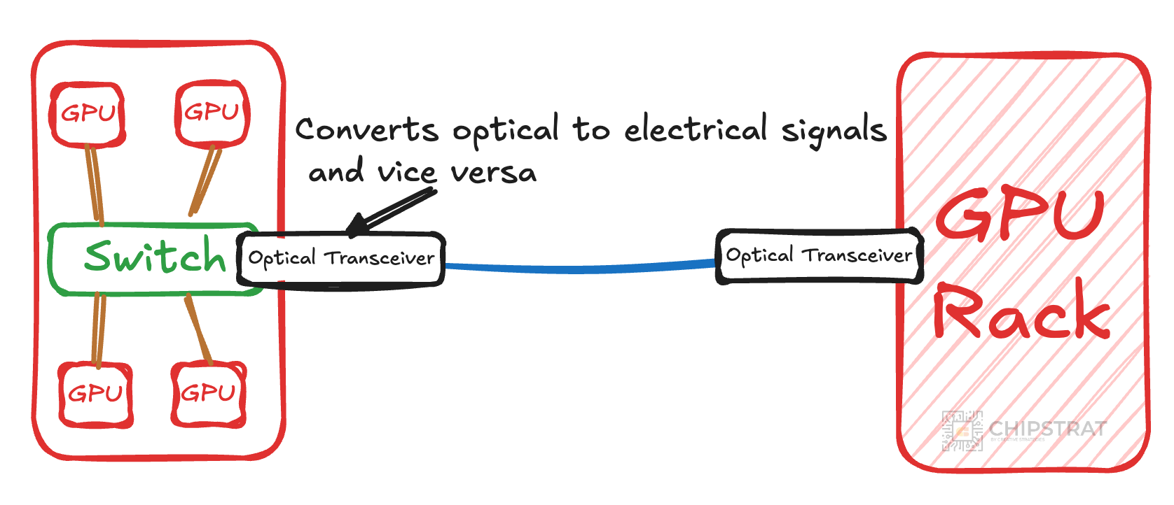
Inside the rack, however, GPUs and switches communicate electrically. Signals travel over short copper traces as high-speed digital electrical signals. Because a rack may contain dozens of GPUs, traffic arriving over fiber must be routed to the correct destination. That routing is done by a switch:
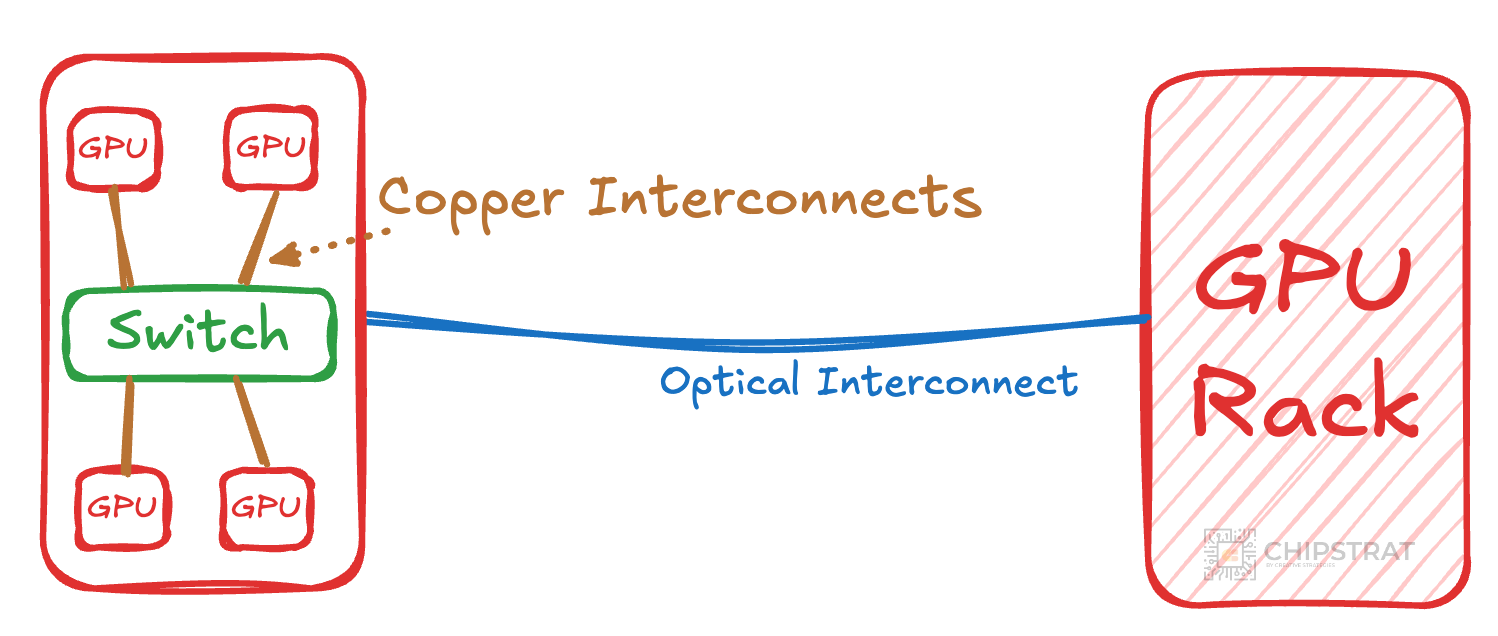
In this example we see two domains; optical signals over fiber outside the rack and electrical signals over copper inside it:
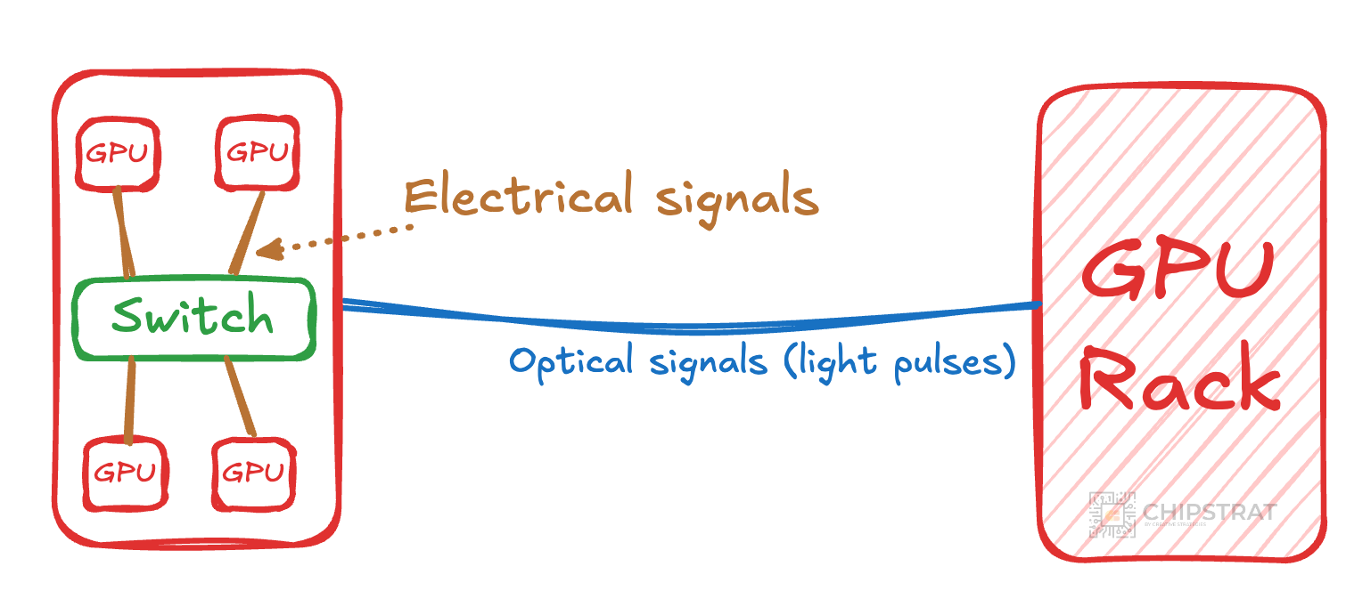
Somewhere, the data must be converted between these two domains.
Where does that happen? The switch?
Good guess! But not quite. Modern switches are CMOS chips that operate entirely in the electrical domain and switch electrical bits, not photons. (Except for TPUs, which use optical switches, but we’ll circle back to that later).
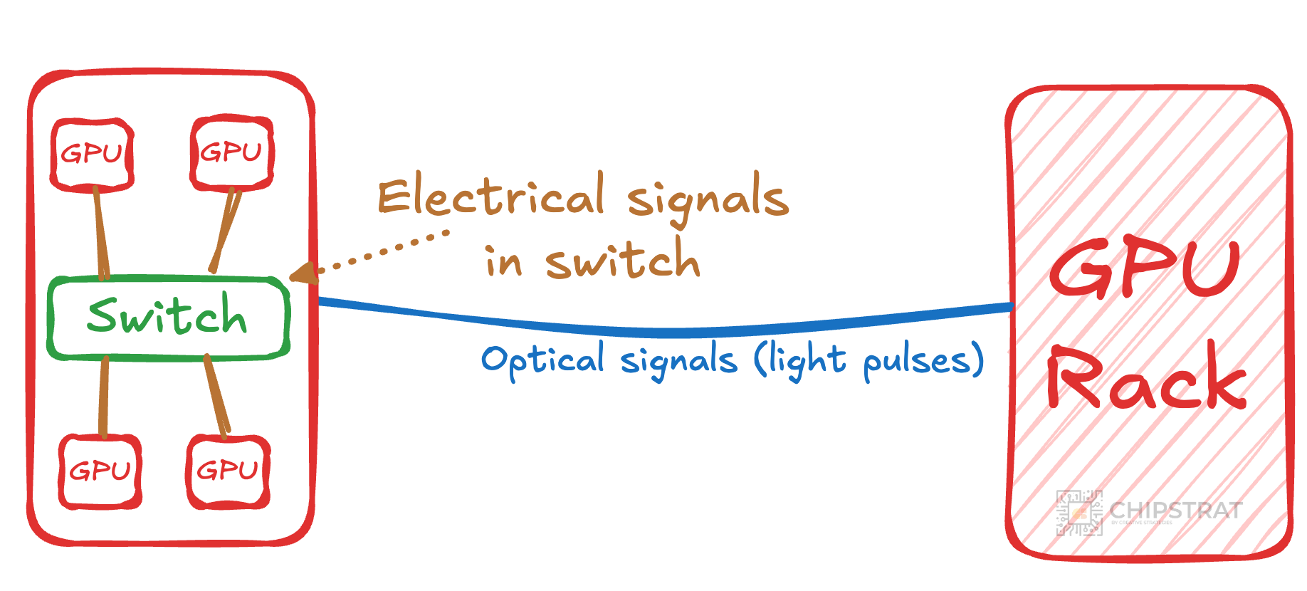
That means the conversion between optical signals on the fiber and electrical signals on copper must happen before the switch.
This is where pluggable optics enter the picture!
Pluggable Optics
A pluggable optical module is a transceiver, meaning it both transmits (Tx) and receives (Rx) data over fiber. As shown in the image above, one end of the transceiver plugs into the switch and the other end is connected to fiber. Hence the term “pluggable”!
On the fiber side, data is carried as optical signals. On the switch side, data appears as electrical signals compatible with the switch ASIC.
So the transceiver’s primary role is to convert data between the optical and electrical domains.
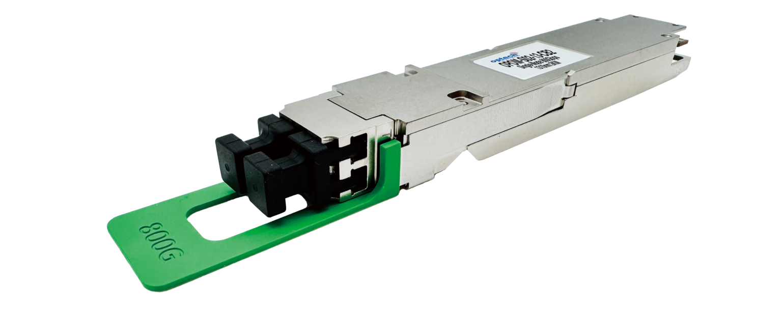
Here’s an example of a standalone transceiver:
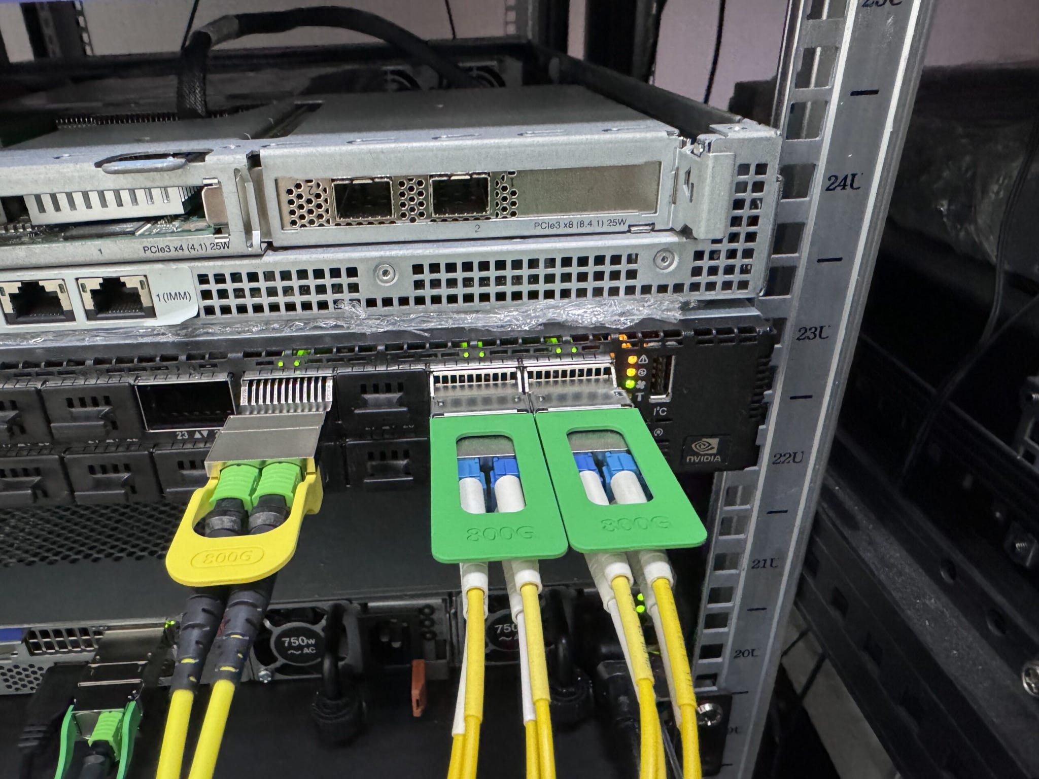
And when wired up to the fiber and plugged into the switch it looks like this:
There are many different types of transceivers, and the names can get unwieldy. Vik has a good explainer here: A Complete Guide to Optical Transceiver Nomenclature
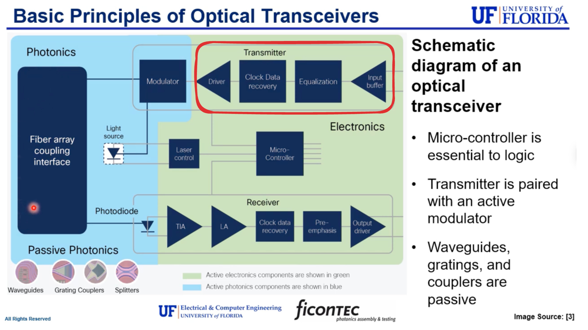
A transceiver has two major subsystems, the optical engine and the electrical engine.
Optical Engine
The optical engine handles photons.
RX (optical → electrical)
Incoming light pulses from the fiber are received by a photodiode, which converts them into an analog electrical signal.
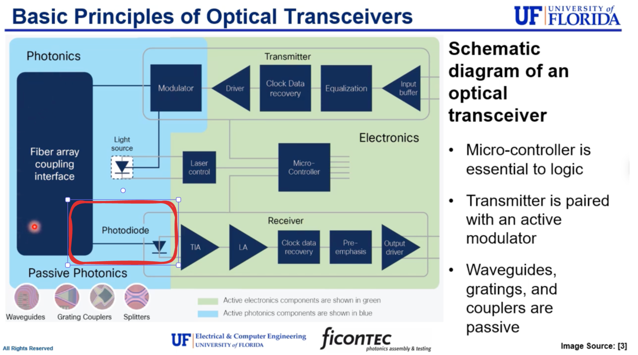
A photodiode is a semiconductor device that absorbs incoming photons and converts them into a proportional electrical current, turning pulses of light from the fiber into an analog electrical signal.
Wonderful basic explainer on photodiodes from Khan Academy:
Deeper technical dive from U of Florida on optical transceivers:
In addition to photodetection, the RX optical engine performs optical coupling and alignment, wavelength filtering in multi-wavelength systems, and basic analog conditioning before handoff to the electrical engine.
Its output is a weak, noisy analog electrical signal. Timing recovery, equalization, and error correction are handled downstream by the electrical engine.
TX (electrical → optical)
A laser provides a continuous light source, and a modulator encodes outgoing data onto that light for transmission over fiber.
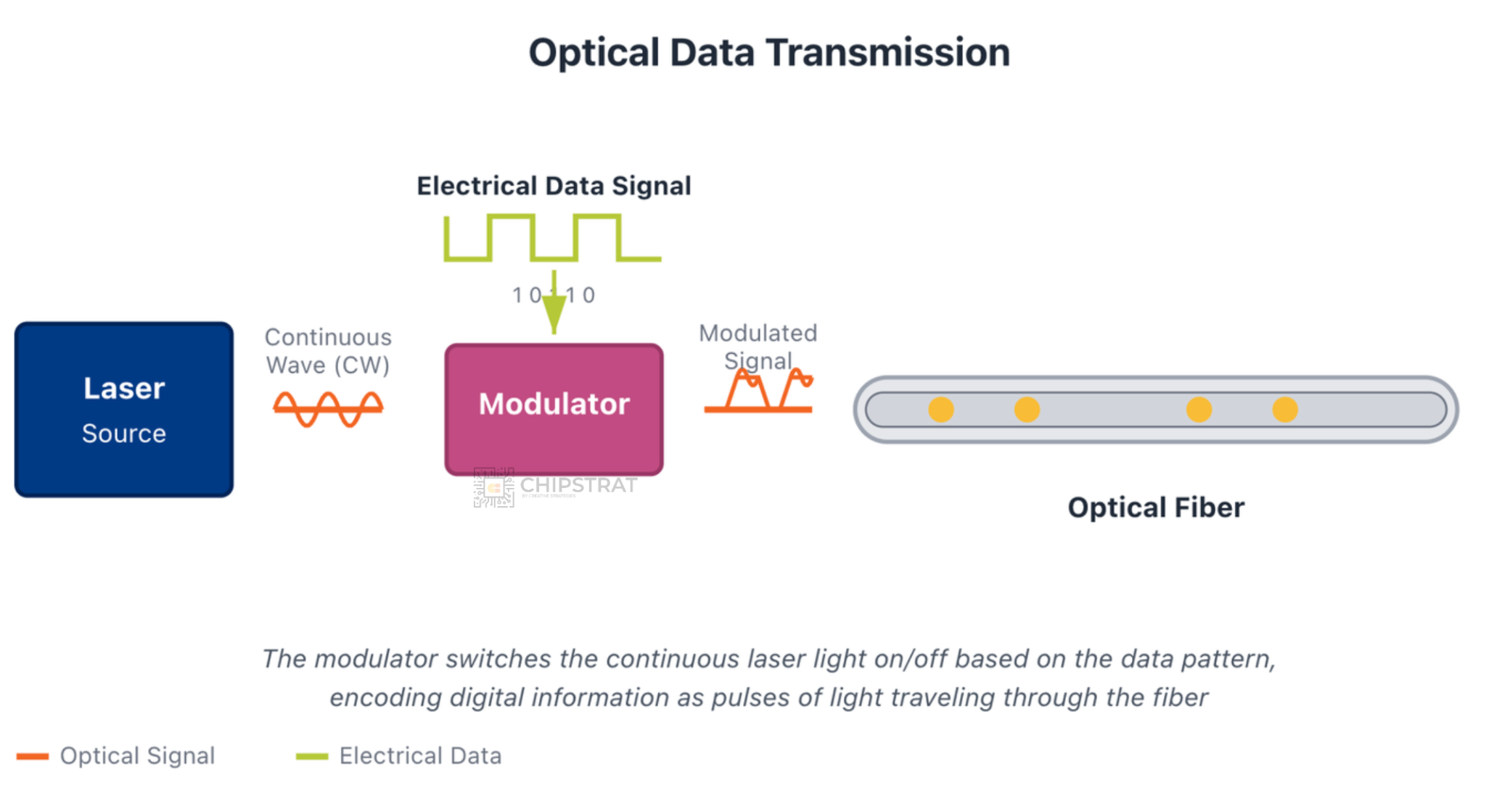
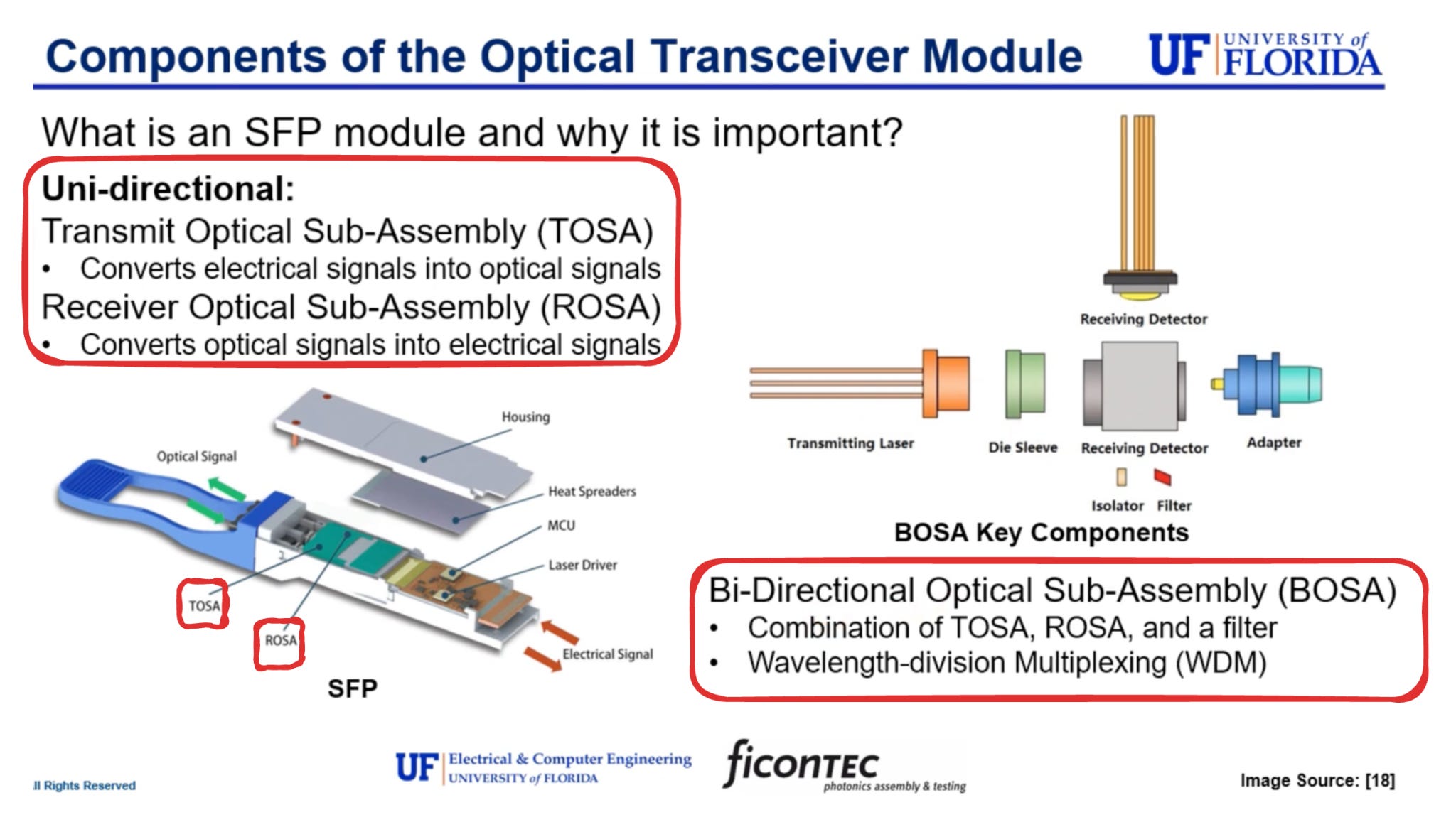
Put simply, the optical engine generates, modulates, and detects light.
It can have separate transmit and receive sub-assemblies, or combine them into one:
Electrical Engine
Once the optical engine has converted light into a weak analog electrical signal, the electrical engine takes over. Its role is to recover clean digital data that the switch ASIC can reliably process and to condition outgoing electrical data for conversion back into light.
At modern data rates, this is the most challenging part of the transceiver.
Conceptually, the electrical engine plays a role similar to that of a DSP in an AEC, compensating for channel impairments to deliver clean digital data, though here the signal originates from an optical receiver rather than a copper link.
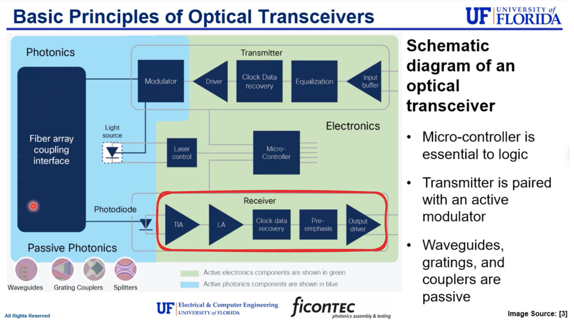
RX (analog → digital)
On the receive path, the electrical engine processes the analog signal from the photodiode. It amplifies the tiny electrical current, performs clock and data recovery to extract timing information, applies equalization to compensate for distortion and frequency-dependent loss, and decodes forward error correction to detect and correct bit errors.
The output of the RX electrical engine is a clean, retimed digital signal driven onto the host electrical interface and received by the switch ASIC SerDes.
TX (digital → analog)
On the transmit path, the electrical engine prepares outgoing data from the switch for optical transmission. It encodes forward error correction to improve robustness over the optical link, applies pre-emphasis and equalization to shape the signal for the electrical channel inside the module, and performs clock alignment and retiming to ensure stable modulation.
In the final stage, the processed digital data is converted into a continuous-time analog electrical signal that directly drives the optical modulator:
In traditional pluggable optics, the electrical engine is DSP-heavy and therefore power-hungry because it must tolerate long copper traces between the switch ASIC and the module, wide variation in board designs and operating conditions, and high per-lane data rates such as 50G, 100G, and beyond. This DSP overhead is what makes pluggable optics flexible and interoperable, but it also drives higher power consumption and added latency.
Why Pluggable Optics?
Traditional pluggable optics are great because they decouple optics from the switch; by placing optical-to-electrical conversion in a removable module, switch vendors could design a single electrical ASIC and support many optical reaches, speeds, and fiber types. Operators can then mix vendors, swap modules in the field, and even upgrade bandwidth without redesigning the switch itself.
And, as Vik notes here, maintainability is everything:
Field data from hyperscalers shows that laser sources are among the top three failure modes in optical systems. In traditional pluggable transceivers, a failed laser means swapping out a front-panel module.
But that same decoupling of optics from the switch is also the source of inefficiency. Everything in engineering is about trade-offs!
Because a pluggable module must operate across many switch designs and board layouts, its electrical engine has to tolerate long, lossy electrical channels:
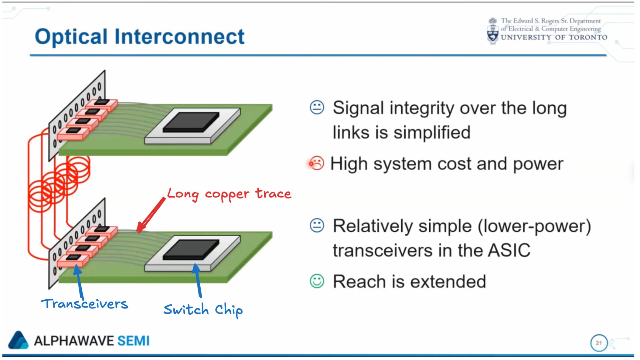
Historically, keeping optics off-package simplified manufacturing, thermal design, interoperability, and field serviceability, even though it imposed an electrical penalty. Note the penalty wasn’t so bad at lower transmission speeds.
Nice reference video from Alphawave Semi:
Alphawave is now officially owned by Qualcomm; the acquisition was finalized last week.
Cleaning up those signals requires DSP. At 50G per lane this overhead is manageable, but at 100G per lane and beyond, a growing share of system power is spent compensating for electrical impairments introduced by the distance between the switch ASIC and the optics.
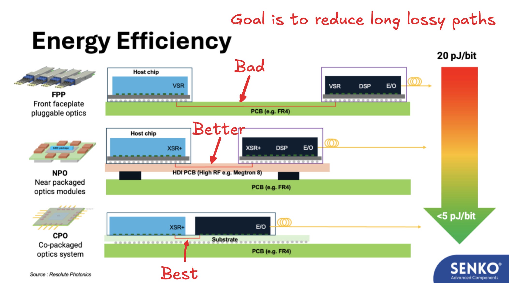
In future articles, we’ll look at how linear-drive optics (LPO) reduce DSP overhead by shortening the electrical interface, and how co-packaged optics (CPO) go further by placing optics directly next to the switch silicon and eliminating long electrical channels altogether:
So in summary, pluggable optics are optimized for flexibility and maintainability. At modern AI-scale bandwidths, that optimization is colliding with power and latency limits.
As a final co-packaged optics teaser, watch this Nvidia CPO switch video and follow the fiber coming into the transceiver, out of the transceiver, and all the way up to the edge of the ASIC.